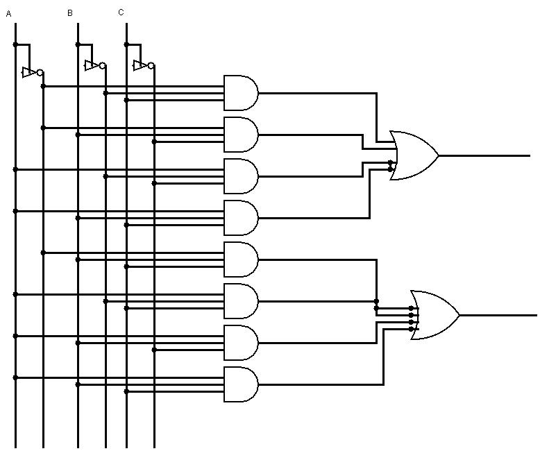
Circuit Diagram Of The Serial Adder
Adder boolean Design full adder circuit using decoder and multiplexer Adder circuit diagram schematic works figure
bcd subtractor circuit diagram - Wiring View and Schematics Diagram
Figure 8.39 block diagram for the serial adder. Serial adder Adder combinational sequential
Adder logic binary circuit gates diagram using array inputs made three twice labeled below used also
Bcd subtractor circuit diagramAdder serial diagram block figure fsm state table transcribed text show Adder serial fsm mealy circuit type moore state using vhdl table fig assignedAdder parallel bit diagram.
Full-adder circuit, the schematic diagram and how it works – deeptronicAdder circuit logic digital using diagram implementation boolean function implement Verilog code for serial adder subtractor unitVerilog code for parallel to serial converter.

Design a 4 bit serial adder detailed schematic (based on the
Uso del flip-flop d en serial adderAdder parallel binary serial bits gif taken stack Adder simplificationAdder registers njit.
Bcd subtractorAdder ripple verilog subtractor overflow binary serial redstone determine begingroup Circuit diagram of proposed full adderFull adder conbinational circuit.
Circuit diagram of the proposed modified full adder.
Serial adder unitSerial adder using mealy and moore fsm in vhdl – buzztech Bit adder signed alu unsigned complement project cs 32 adders two note both courses cornell edu4 bit parallel adder circuit diagram.
Adder serial subtractor vhdl registers flop schematics simplifiedFull adder circuit diagram Multiplier serial flops addersAdder serial subtractor module schematics.

Bit circuit register shift adder subtractor adders lab shifter
Adder circuitverseSerial adder bit diagram two Adder truth vidi circuitdigest vidilabA 5 bit wide bit-serial multiplier using carry-save technique. m, s and.
4-bit serial adder/subtractor with parallel load – altynbek isabekovDigital logic design: full adder circuit Combinational and sequential design of a 4-bit adder. (a) ha circuit4-bit serial adder/subtractor with parallel load – altynbek isabekov.

A binary adder made using and-or array logic
Half bit using four adders adder circuit schematic circuitlab created logic digitalDigital logic Cs 3410 spring 2018 project 1Cs201 design adders lab.
Binary adder and parallel adderDesign of parallel adder 12+ half adder schematic20+ full adder block diagram.

Full adder circuit diagram
Full adder in digital electronics .
.


Verilog code for parallel to serial converter - mertqarrow

Full Adder Conbinational Circuit | All Computer Topics

bcd subtractor circuit diagram - Wiring View and Schematics Diagram

digital logic - 4-bit decrementer using four Half Adders - Electrical

Combinational and sequential design of a 4-bit Adder. (a) HA circuit

Design Full Adder Circuit Using Decoder And Multiplexer - Wiring Diagram